
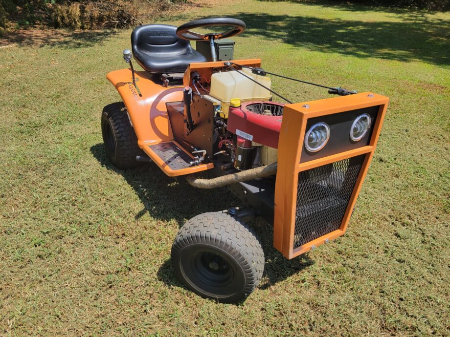
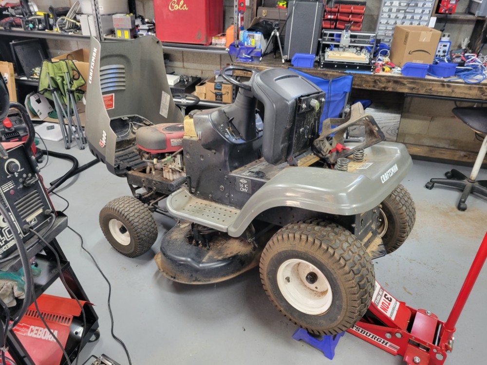
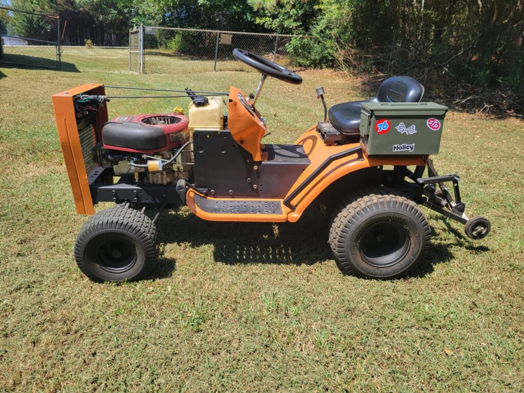
This is my modified lawn tractor. I got this early 2000’s Craftsman lawn mower and I’ve been wanting to make a “mud mower”. This basically means a typical lawn mower that has been modified and upgraded. These upgrades include bigger tires, higher top speed, etc. Lawn mowers provide a great starting platform for this because they are cheap, have plenty of replacement parts, and generally have powerful motors. This Craftsman mower came equipped with a 16HP Briggs and Stratton engine.
Tear Down
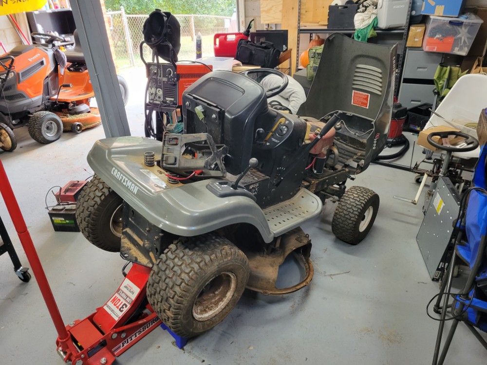
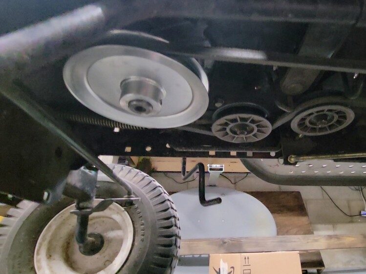
The first thing I took care of was removing the mowing deck as I no longer need that. This involved removing a couple pins, taking the belt off, and lowering the deck out. Once I had this removed, I could get to the drive pulleys and drive belt. I verified everything looked good and the mower could at least drive under it’s own power. Then I started planning the pulley swap.
Pulley Swap
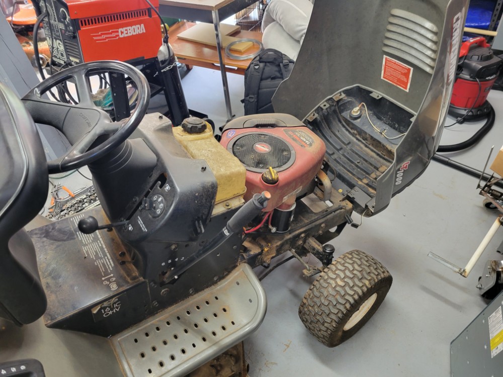
Lawn mowers are geared for high torque. The engines typically run around 3600RPM for peak power. This ensures the motor can keep the blades spinning fast enough to cut the grass. The motor connects the rear trans-axle with a belt running the length of mower. A small pulley on the engine shaft and a large pulley on the trans-axle means there is enough gear reduction to allow the driver to shift through the gears at a reasonable speed for cutting the grass. Without the need for turning the deck, and the desire to go faster, I simply have to change the pulley sizes so that the motor pulley is larger and the trans-axle pulley is smaller.
After searching around, I purchased a 6″ pulley to fit on the motor and a 3″ pulley for the rear. The front pulley required a key-way key and the rear did not, as the shaft was already keyed.
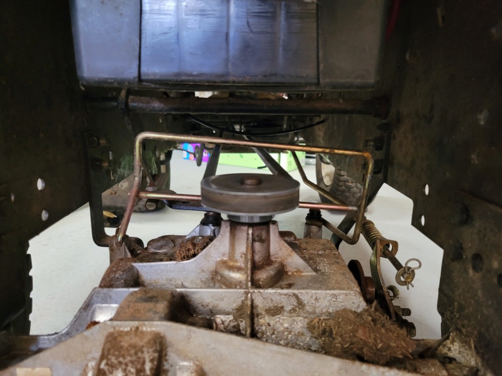
I was able to reuse the existing deck belt, so I didn’t have to purchase one. With this setup, I took the mower for a test drive and was very pleased with the 6 speed transmission. The 1st gear was lower enough that I could crawl very slowly and the 6th gear was tall enough that I could get the mower up to speed. After tightening everything down and rebuilding the brakes, I took the mower around the block to test the top end. The top speed of 32MPH was very impressive and extremely sketchy.
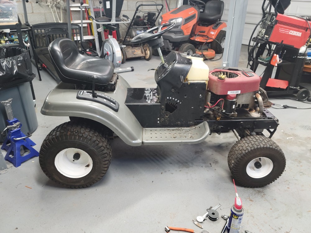
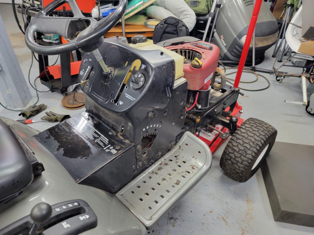
I got the mower cleaned up and scraped the gunk off it so I’m not having to touch it the whole time I’m working on it. I was surprised to find out the wheels are actually white and not brown.
Adding a Gas Pedal
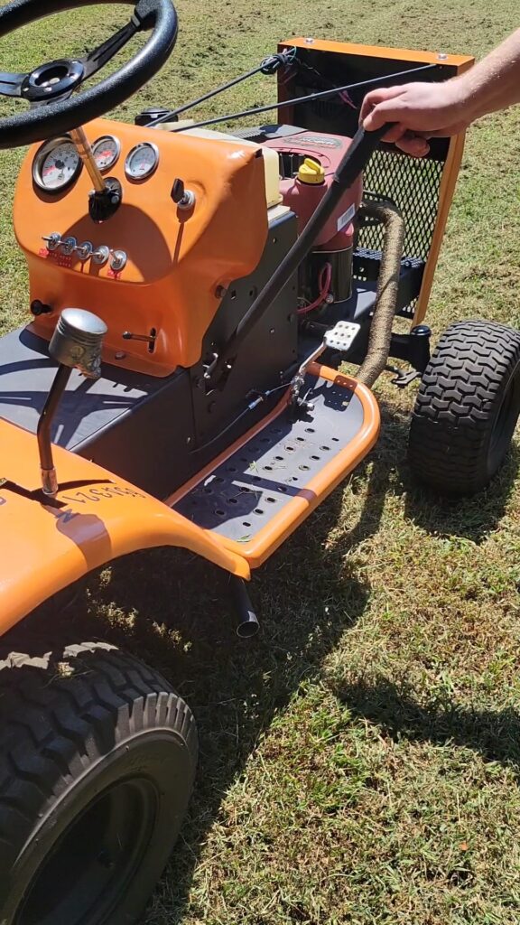
Next up, I took out the stock throttle control and installed a go-kart style throttle pedal. Then, I ran a new throttle cable and bypassed the governor and choke. I ran this down to the running board where I welded a couple brackets to hold the pedal and cable.
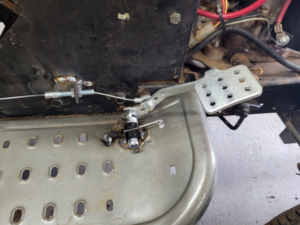
By tweaking the the placement,I found a comfortable place for it and I adjusted the action of the cable using the holes in the pedal arm. Lower down, I have less movement, and higher up there is more. This allows the throttle to be fully open when the pedal is completely depressed, but without putting strain on the throttle plate.
Bypass Safety Switches
Most lawn mowers have a variety of safety switches. These include preventing the user from starting without the clutch depressed or starting with the blades engaged. Newer mowers also prevent you from mowing in reverse unless the key is in the correct position and not to forget, getting off the mower without the brake engaged also causes the engine to turn off.
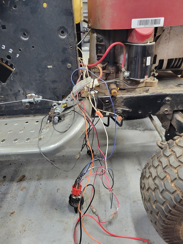
And since safety is just another word for inconvenience, I removed all these. I directly connected the starter relay to the switch and using the wiring diagram I bypassed the switches.
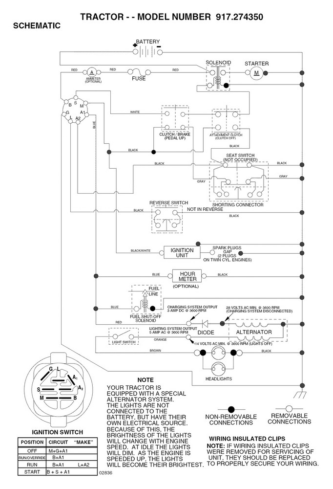
Here is a copy of the stock wiring diagram. I replaced the starter switch with a car-style switch. The primary difference is the mower connects the magneto to ground when switched off, this kills the ignition. Since this is the opposite of a car, I used a relay that is “normally-on” connected to ground. So when power is cut, the magneto is held to ground and kills the motor. Without this, the fuel solenoid would be what kills the engine. The engine would continue to run until the fuel in the carburetor was used up.
Ignition Switch
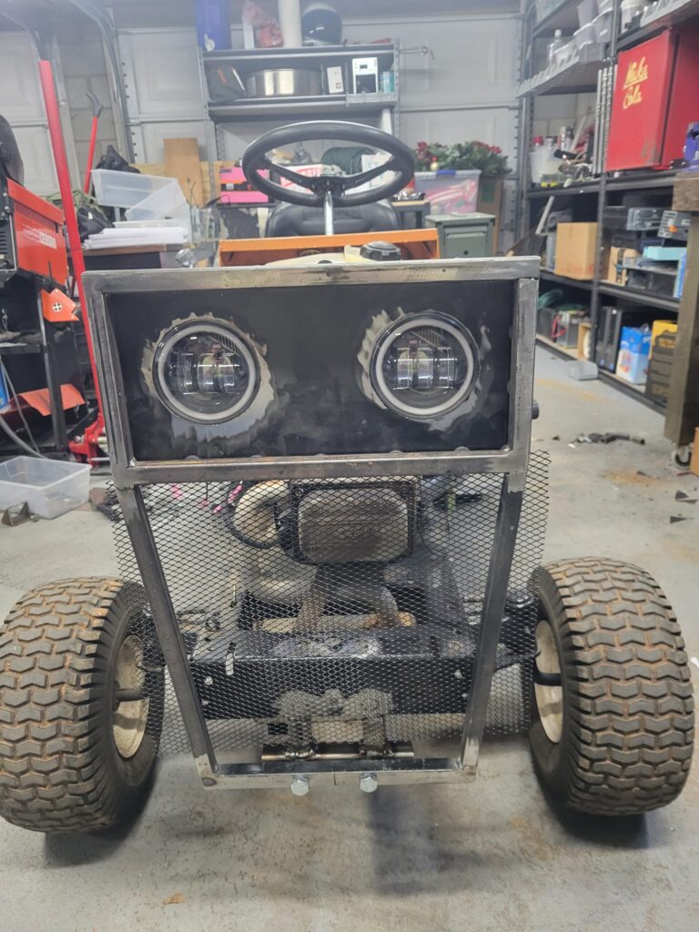
This ignition switch also allows for “accessories”. This will include under glow lights as well as dash lights and headlamps.
Lawn mowers are actually very simple electrically, and the bulk of the complexity is due to the safety switches. The alternator has two sets of coils with a center tap to ground. One circuit is for charging the battery at 3A and the other is 5A for running the headlamps. These ratings are for 3600RPM however, when idling the power output is much lower. This will be a consideration when running electrical for dash lights and for the LED headlights I plan to install.
The headlamp circuit also is not rectified. So this is 14V AC powering the headlamps. The primary issue is the LED headlights are DC. I will have to use a full wave rectifier to get the most back out of the AC signal. This will be tricky since the center tap is tied to ground at the alternator.
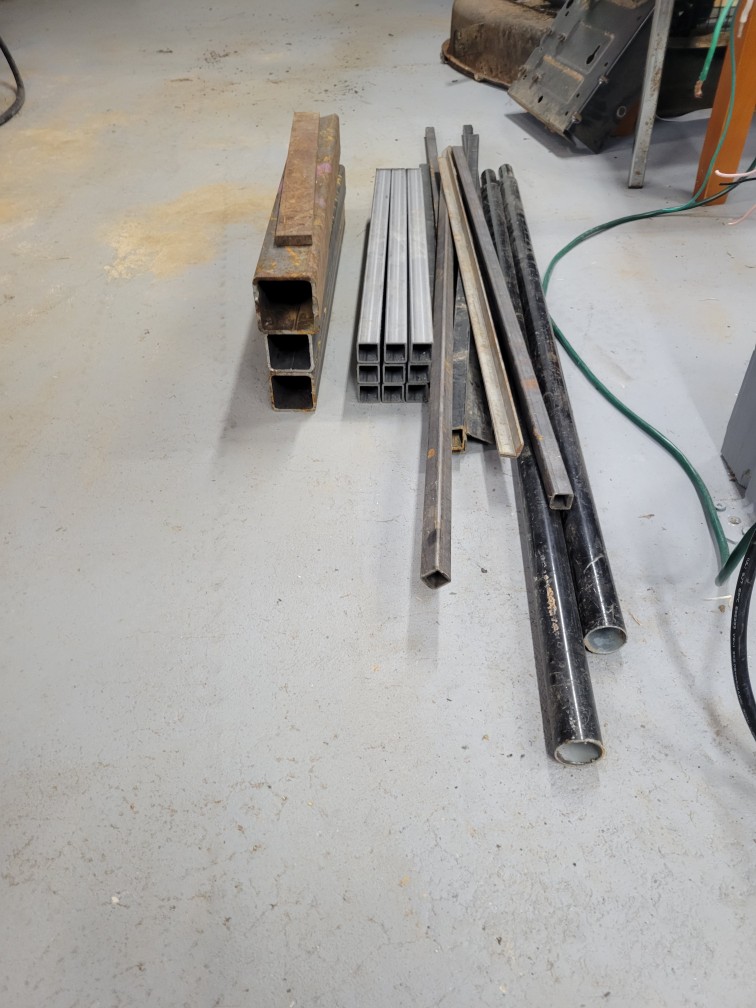
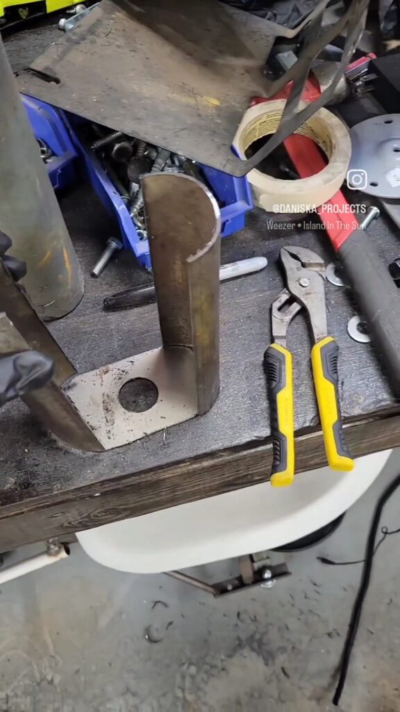
A trip to the scrapyard yielded me a small assortment of metal. Mostly square tubing. The round tubing I plan to use for a new exhaust system. The larger square tubing for a hitch and bumper. And the medium square tubing for reinforcement and implements.
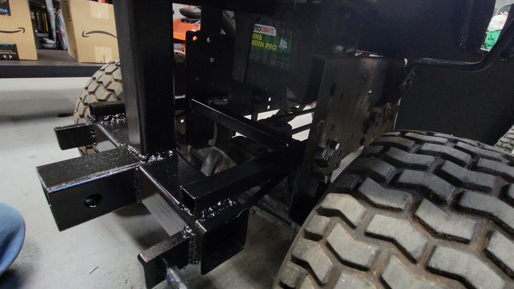
Custom 3 Point Hitch
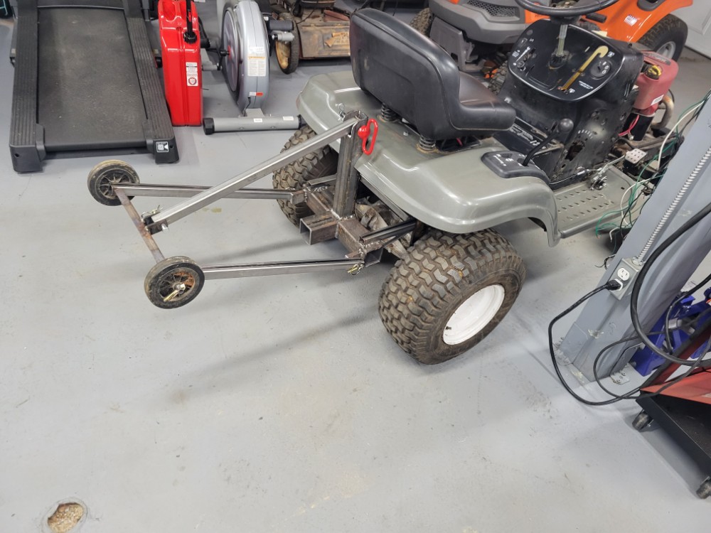
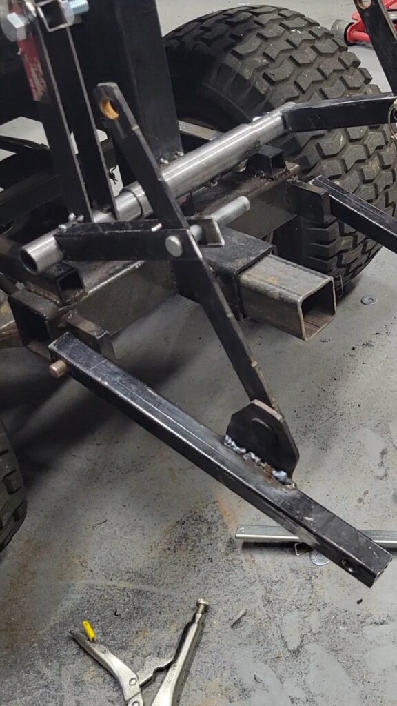
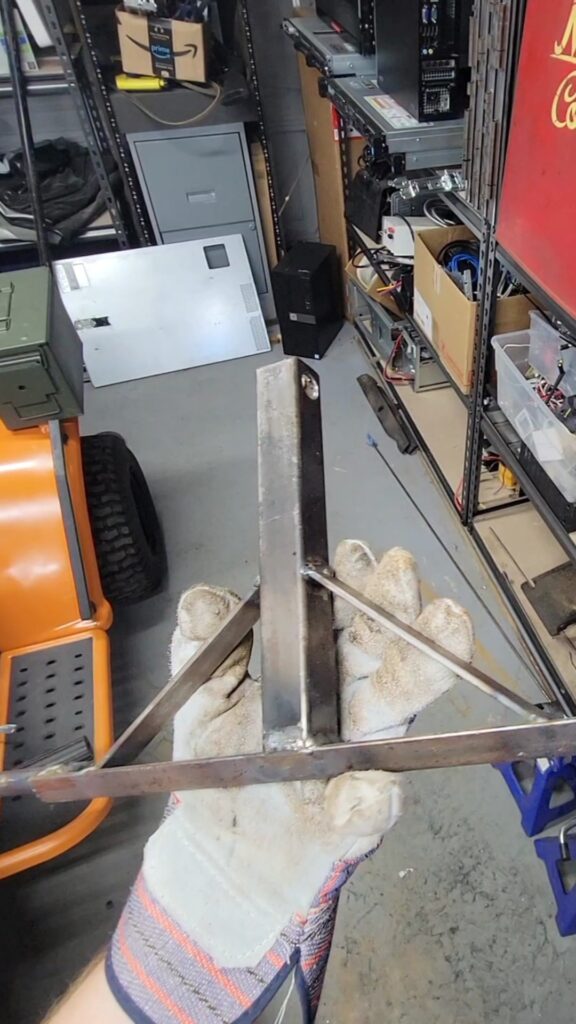
After some horsing around with the mower, I quickly realized I may need some kind of wheelie bar. And by that, I mean I nearly flipped the mower after attempting a wheelie. I wanted a multi-purpose attachment. I envisioned a sort of bumper, that included a hitch. This would attach to the mower’s frame. It would also be similar in design to a standard tractor’s 3 point hitch. I made two lower points and a single higher point. Using the scrap pieces, I made this contraption. Once I got the hitch tacked together and test fitted everything, I welded the whole thing up solid.
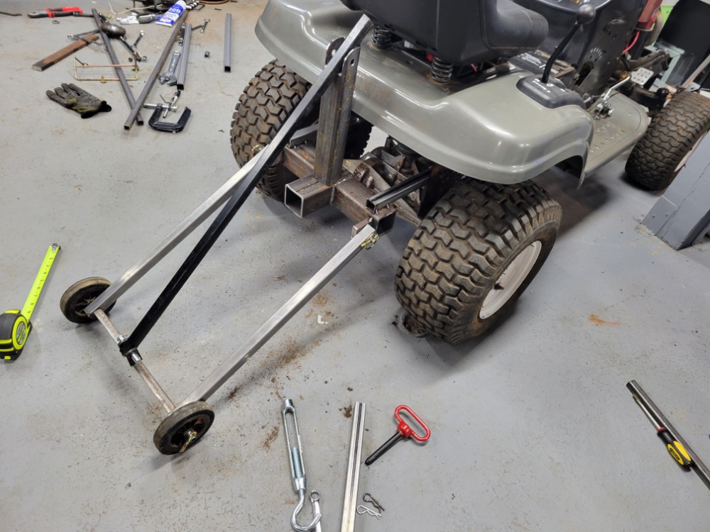
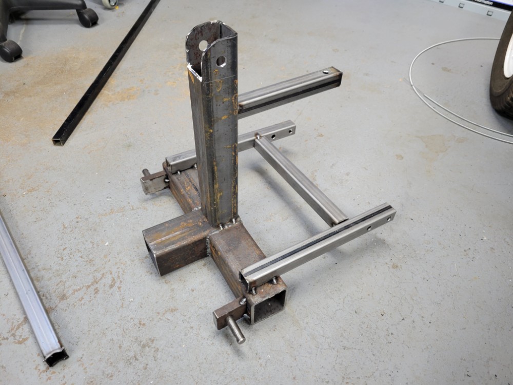
I painted the hitch assembly a semi-gloss black and it turned out very nice. I also painted the wheelie bar and it turned out nice as well.
Shifter Cutout Fix
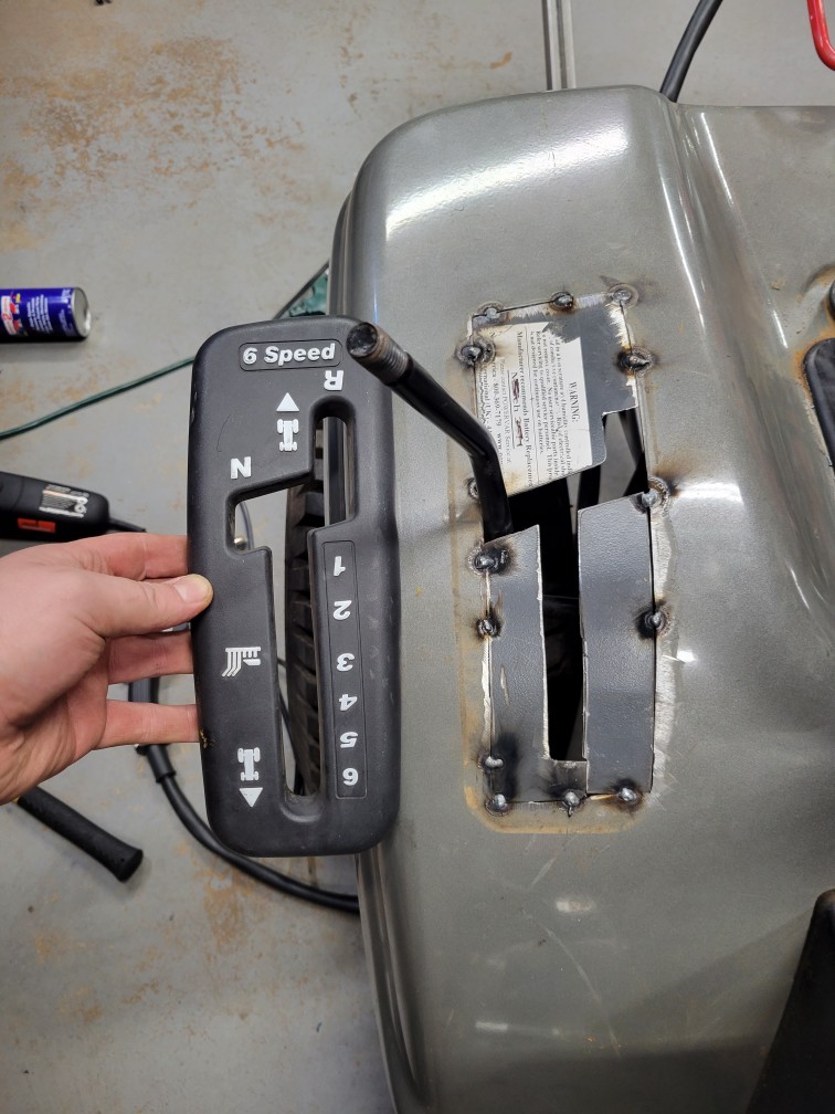
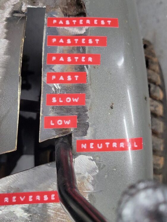
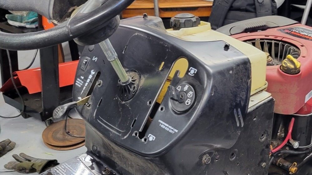
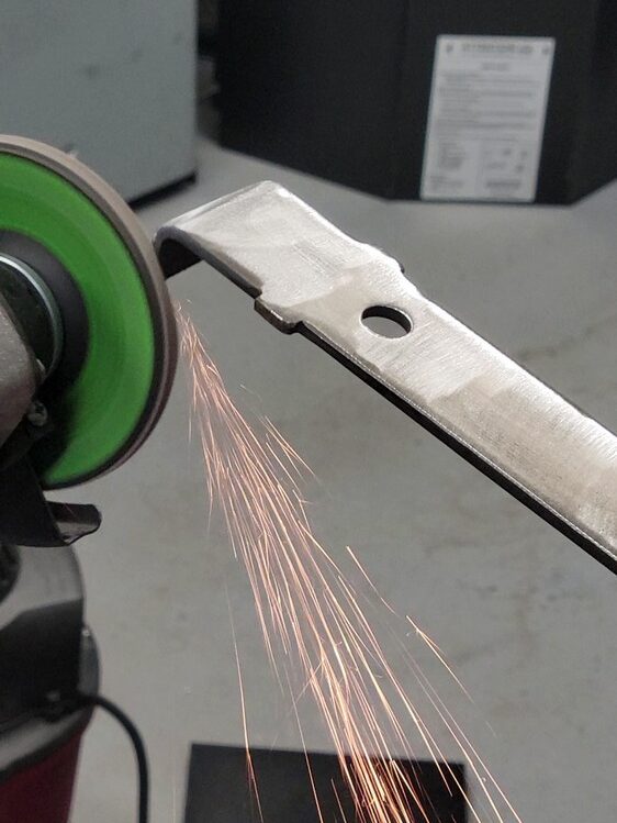
I was unhappy with the plastic gear shift pattern. There was nothing inherently wrong with it, more for cosmetic reasons I removed it and filled the hole with metal to reproduce the shape.
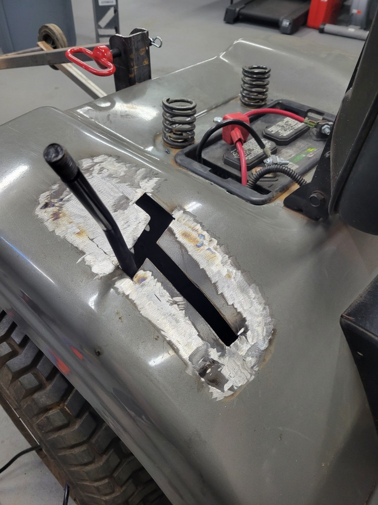
I will clean up the metal when I finish the body work. Plan to fill in the low spots with bondo and sand smooth.
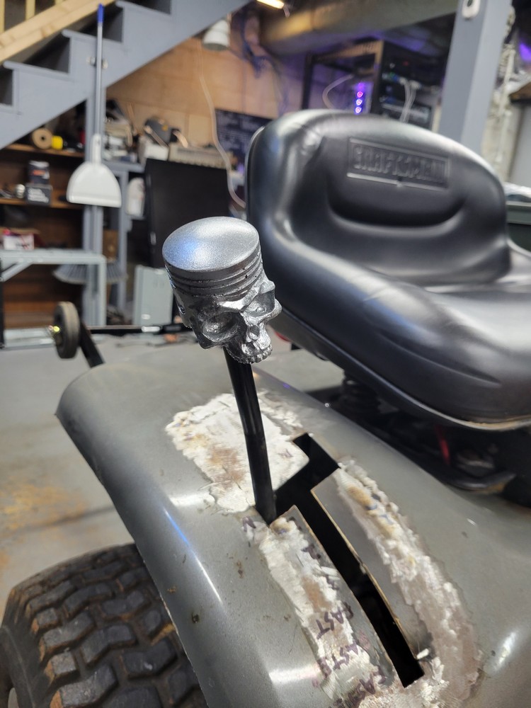
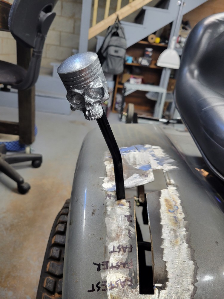
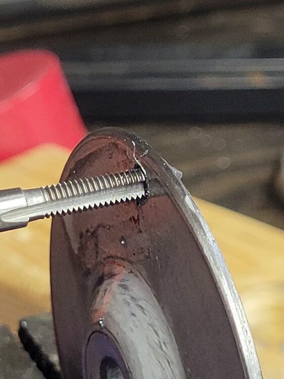
To make the mower edgier, I added this custom piston skull shifter. I made the mold for it a while back and so I used one of the resin casts for the shifter. So I smoothed the top over by sanding it so it’s easier on my hand and then drilled a hole up through the bottom nearly to the top and used a 1/2″ tap as far as it would go, then I spray painted it silver. In my daily car, I prefer a ball shifter, so it’s nice to be able to use this design in a project.
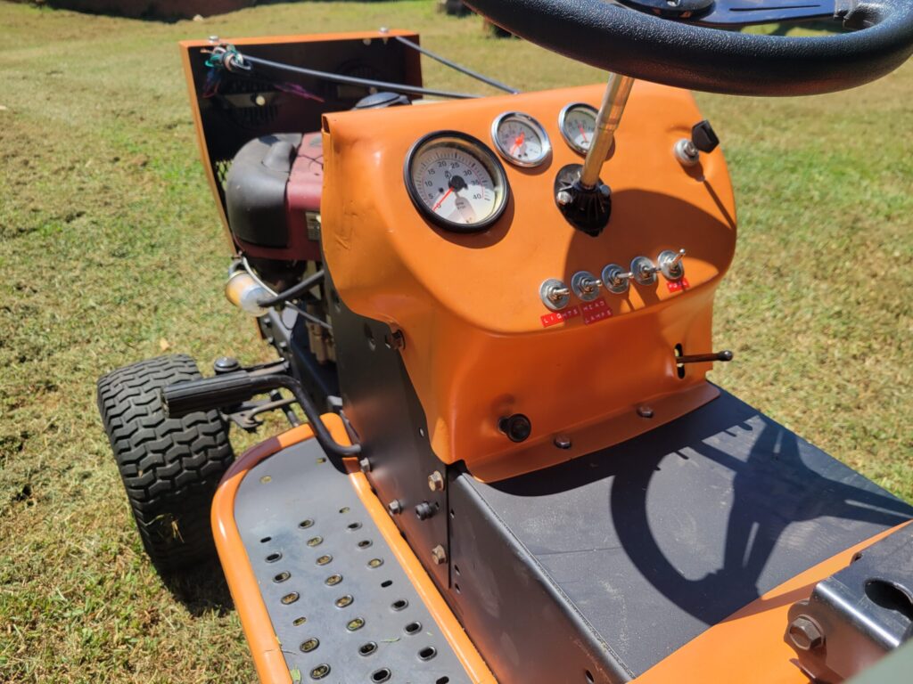
Dash Modification
My original idea for the dash was to rebuild the entire thing from scratch, after some consideration, I opted against this idea. I decided to modify the original dash. I wanted to add several gauges and toggle switches. As well as add the new ignition switch.
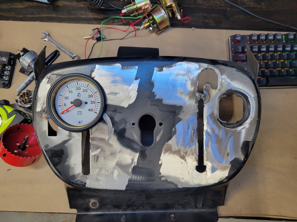
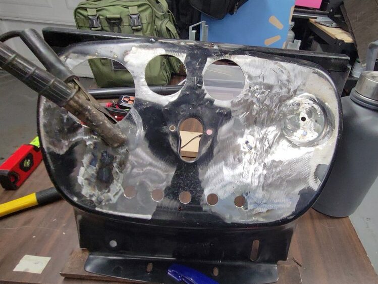
I started by welding up some of the smaller holes in the dash. I then used an 85mm and a 52mm hole saw to drill out the holes for the gauges. The primary gauge being the tachometer. I also drilled 5 small holes along the bottom for toggle switches.
From here, I began to fill in the larger areas with metal. This involved cutting out templates of the shape to fill, then cutting them out of metal and welding in place. And finally grinding down the welds as smooth as possible.
I was able to get the metal reasonably smooth, but ended up using body filler to try to level out the surface. After sanding the body filler down, I coated the entire dash with primer and wet sanded with a 1000-2000 grit sandpaper to better identify high and low spots. Several coats of this high-build primer later, I called it a day and painted the dash with a nice coat of orange.
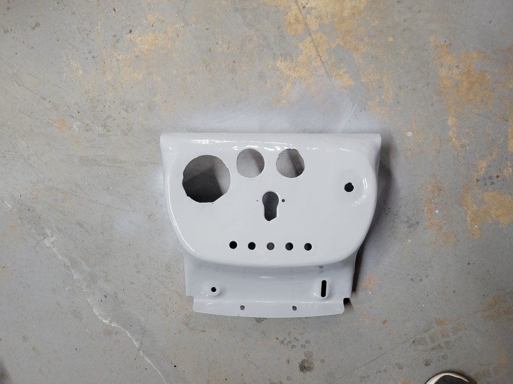
I let the paint dry overnight and then proceeded to start assembling the dash. Some spots had a few pits, but after all, it’s a lawn mower, so it will be okay.
Gauges & Switches
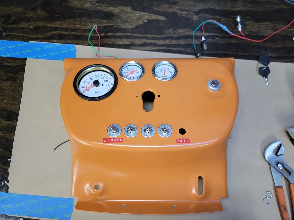
The smaller gauges include a temperature gauge and an ammeter. The ammeter measures up to 30A so a bit of an oversight as the mower’s charging circuit only puts out 3A.
I then continued installing the ignition switch and toggles. I put the fuel solenoid on a toggle so that if I ever intend to store the mower, I can cut the fuel and let the engine use up the fuel in carburetor so it doesn’t gum up.
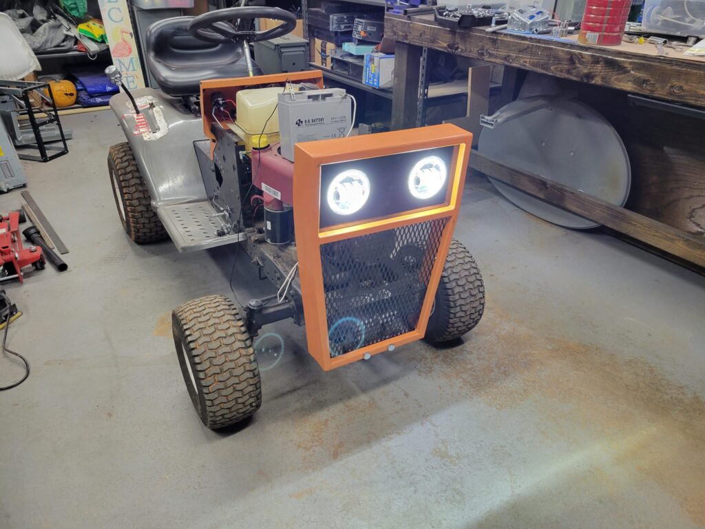
The remaining toggles will be under glow, headlamps, and lights. The main lights switch will turn on the halo lights on the headlights as well as the dash lights. The under glow will be an RGB LED strip mounted to the frame.
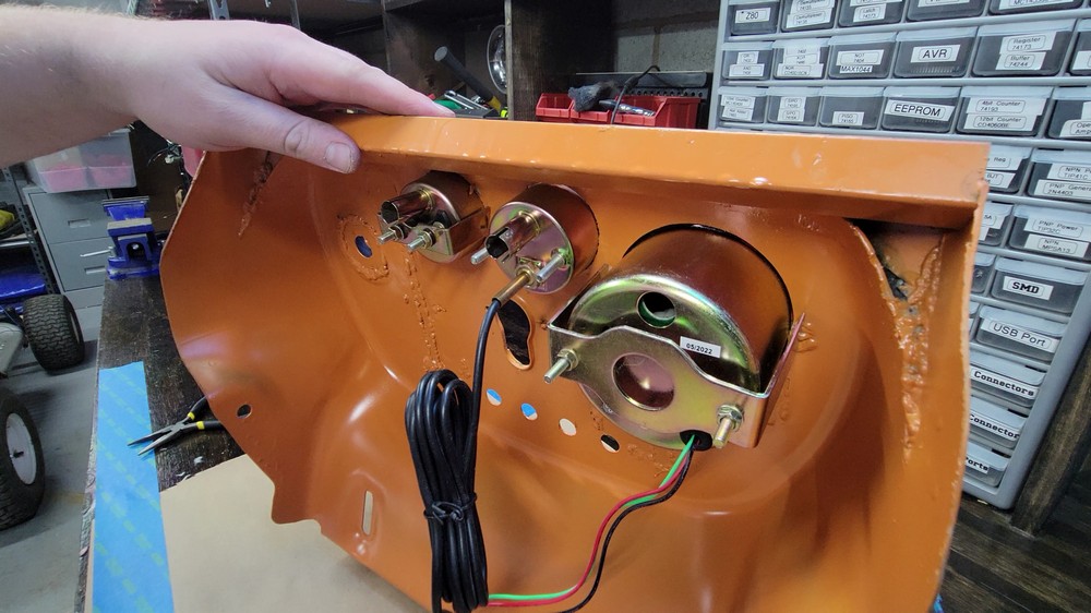
The temperature gauge is analog so I will also have to make a bracket that mounts to the motor in some way to allow the probe to heat up. It typically is used to measure coolant temperature. Since this motor is air cooled, that is a bit difficult to do.
Steering Wheel Upgrade
I was not a fan of the stock steering wheel, so I chose a go-kart style steering wheel from Amazon. This required that I make an adapter plate to mate the existing steering column to the new wheel. I used an old Ikea mounting plate that I had thrown in the scrap pile some time ago. It was very sturdy already had a center hole.
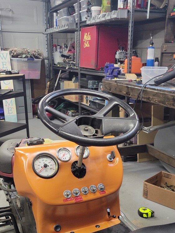
I stared by removing the old steering wheel bolt and washer. The tricky part with replacing the steering wheel is getting the wheel to line up straight with how the mower drives. With the stock setup, the column is slotted as well as the wheel. This allows for more fine tuning. Since I am removing one of these slots, I’m going to have reduced control over how the wheel lines up.
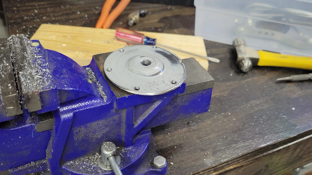
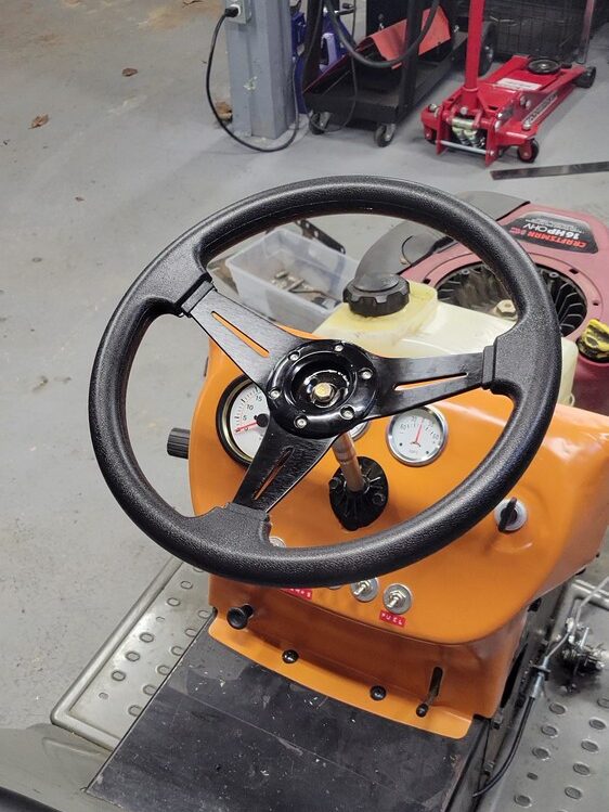
Using the provided plastic cover, I marked the 6 holes onto the Ikea plate. From there, I drilled and tapped each so the steering wheels hardware could be screwed into it. I also drilled out the center hole to accept the steering column bolt.
The steering shaft near the top has two flats on either side to avoid rotation, I had to ensure the mower was pointed straight, and then mark the flats so I could weld two small brackets onto the Ikea plate to prevent rotating.
Added Storage
To add some storage to the mower, I used an old ammo can. I grabbed a bracket that came off the original mowing deck and after cutting it to size, I proceeded to grind off the paint on the fender to weld the bracket to the fender.
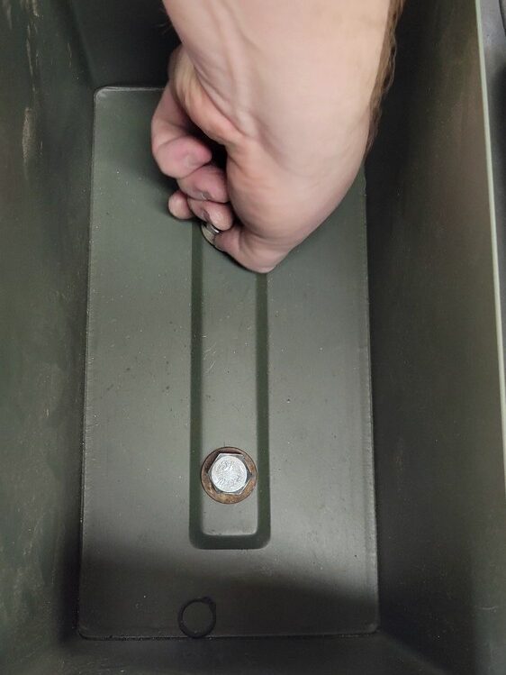
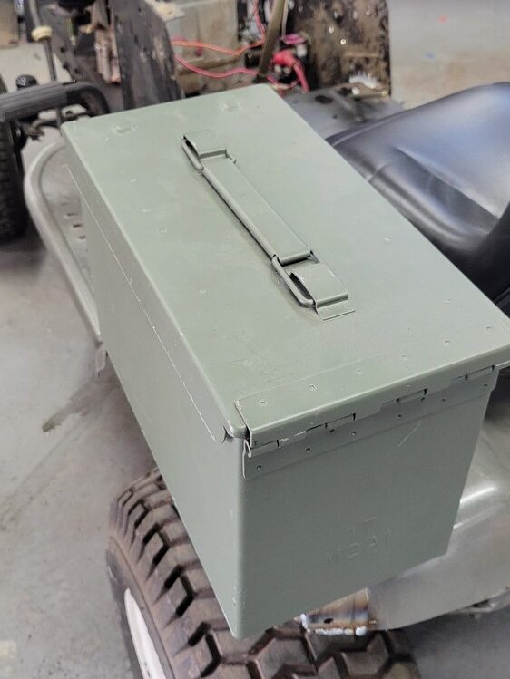
I used the existing holes in the bracket and then drilled two holes in the ammo can. Using 1/2″ bolts, I fastened the can to the welded bracket. This simple addition acts as an arm rest, and helps keep me from sliding off when making sharp turns at speed.
Locking the Axle
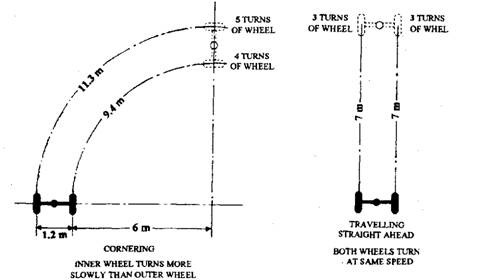
Lawn mowers use a trans-axle to provide power to the rear wheels. This is a transmission and a differential in a single unit. Ignoring the transmission, the differential in a vehicle allows the wheels to spin at different rates when turning.
See graphic, when turning, the wheel on the outside turns more. This is great until you encounter sand or some low-friction surface on one tire. This tire will spin while the other does not. For cars, a limited slip differential may be used, this allows for both wheels to put power to the ground under load, but still allows for different spin rates when turning.
The easiest solution to keeping one wheel from spinning, is to weld the differential. This certainly has it’s pros and cons. This will allow for better traction in dirt or sand, but will make sharp turns difficult.
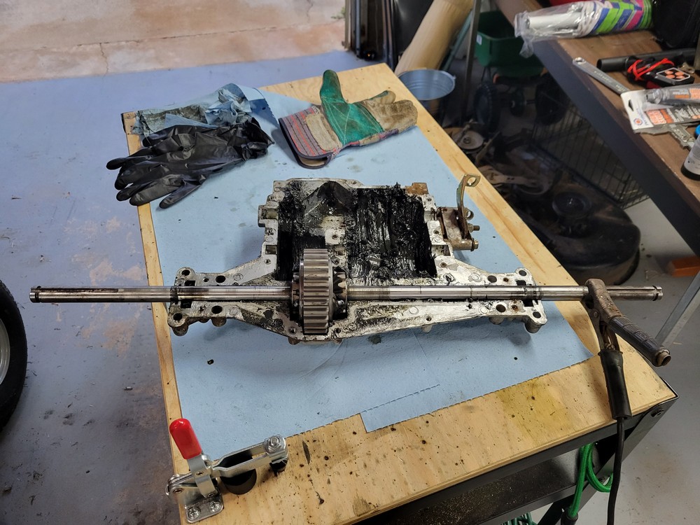
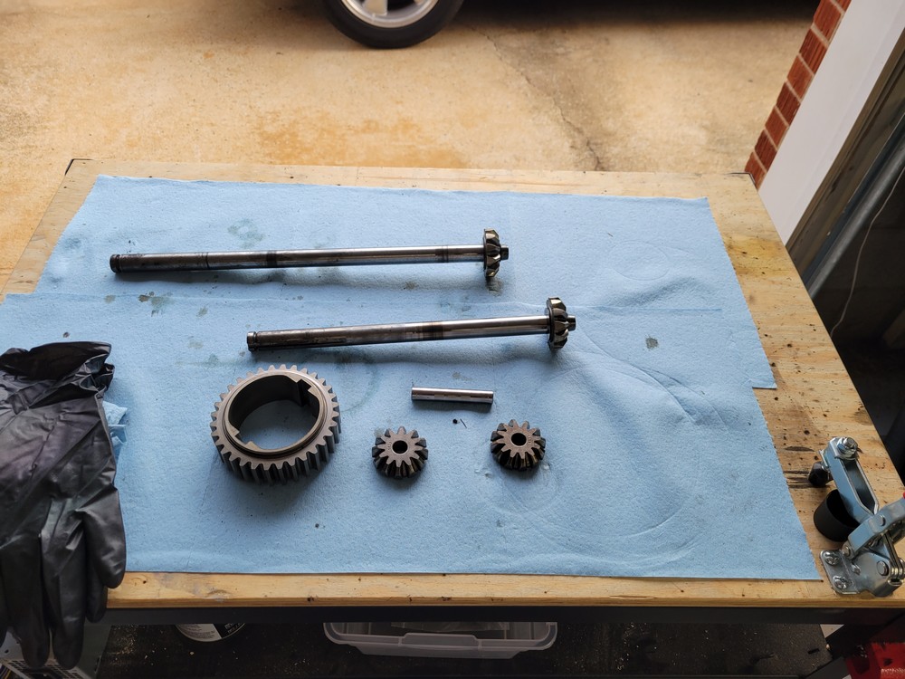
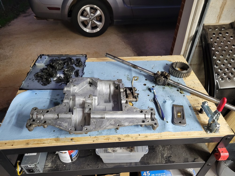
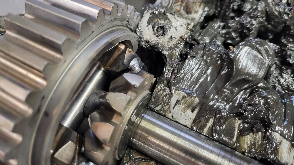
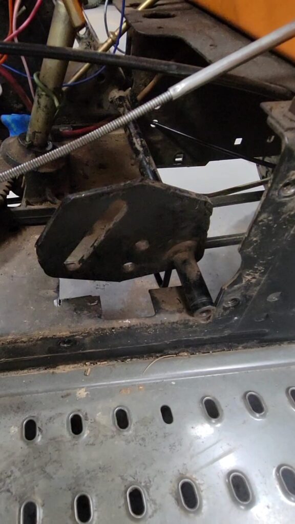
I removed the trans-axle and disassembled it. After getting the case open, I removed the crown gear and planet pinion gears. I used brake cleaner to clean all the parts and remove all grease. After cleaning the case, I placed the gear back into the case and placed a couple tack welds to hold everything together. I then removed the axle and welded everything up solid.
After I finished welding, I reassembled the gearbox and reused the existing grease as I was unable to locate a local supplier for the bentonite based grease recommended.
The welded differential has removed wheel spin when taking corners in dirt, but also makes it more difficult to pull into my garage. With the axle spinning together, the mower wants to continue forward instead of turning.
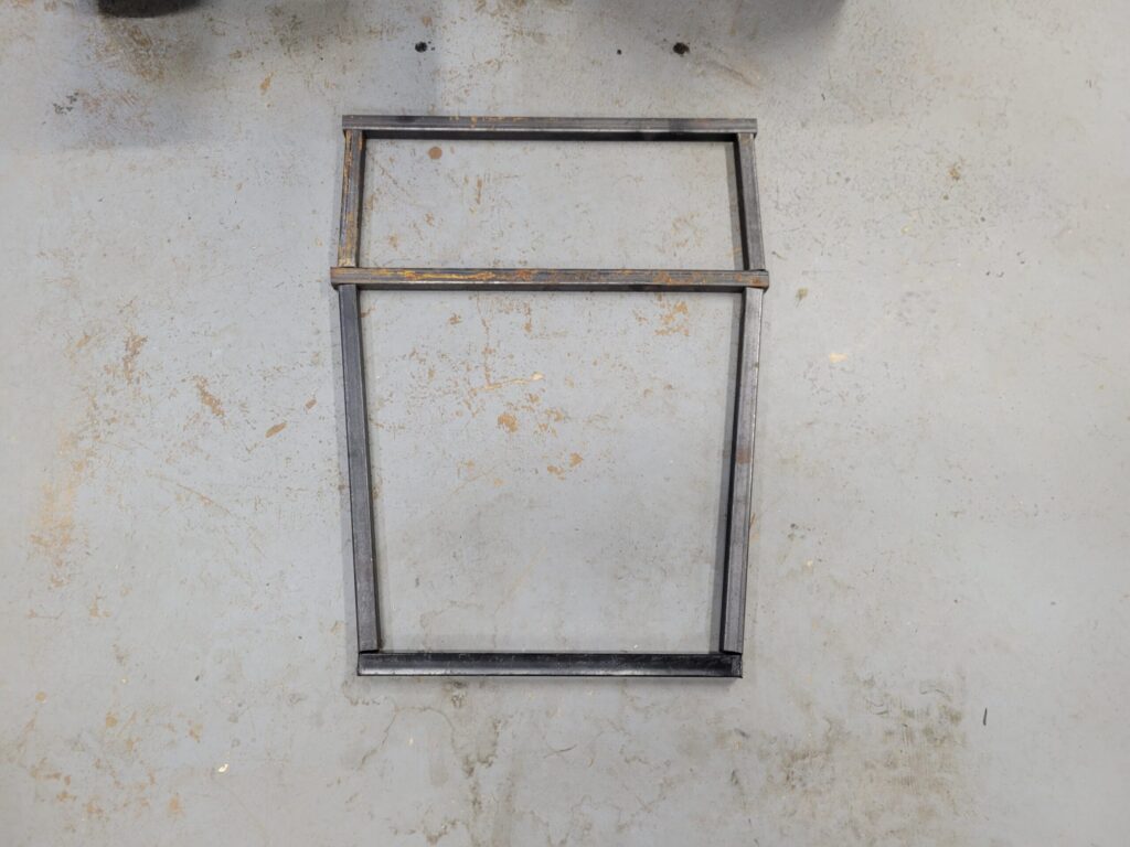
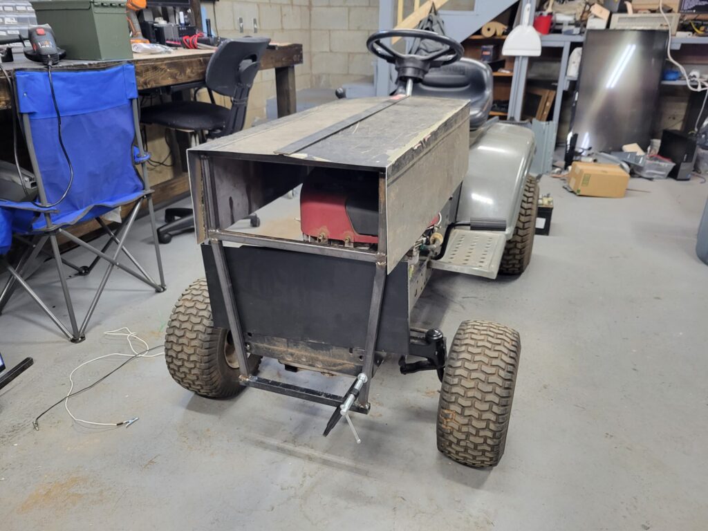
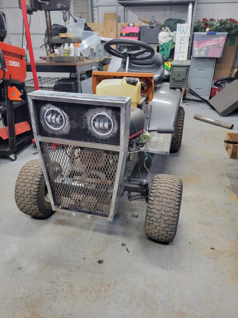
Grille

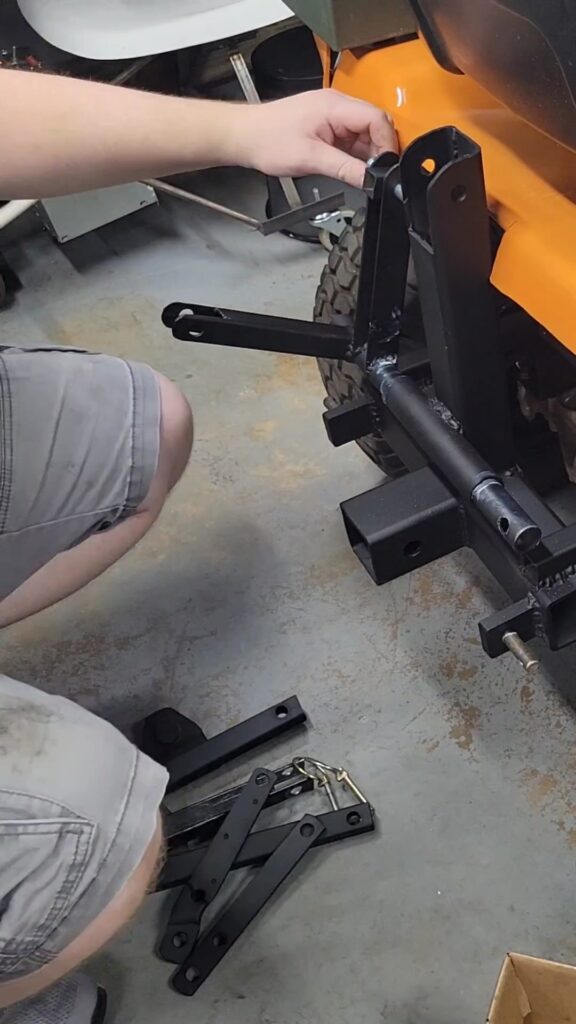
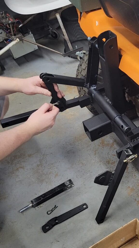
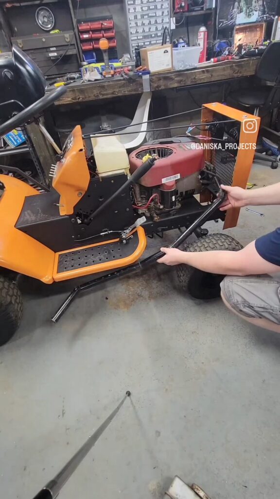
Upgraded 3 Point Hitch
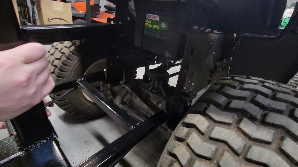
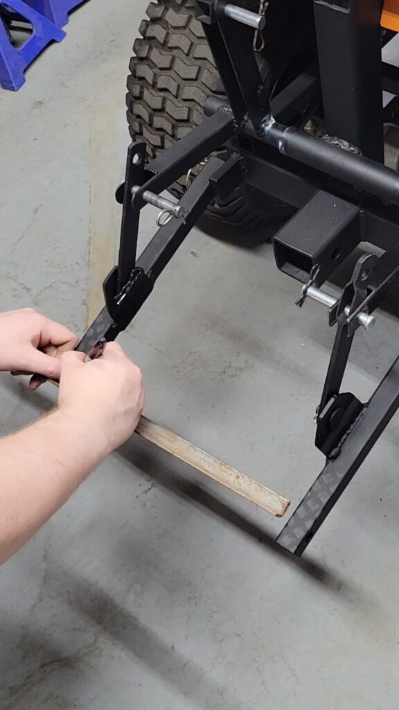
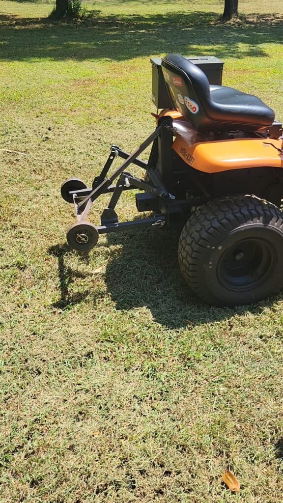
I had the idea of making different implements for the mow-kart, while I already have a wheelie bar, I wanted to make it adjustable. Another idea is a scrape blade that I can raise and lower. Ideally I’d like to reuse the existing deck lever for this. So I drew up some designs and began making the modifications.
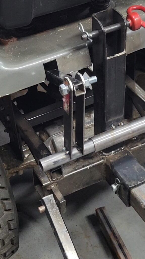
Using scrape metal, I made some parts to raise and lower the trailing arms. I ended up cutting down the existing arms for this. A longer piece of square tubing runs to the front and attaches to the mower deck lever. This back and forth action translate to an up and down motion of the trailing arms.
The first “attachment” I made was a new wheelie bar. I reinforced and redesigned this as I’ve broken several up to this point. I did reuse the wheels since they were decently tough.
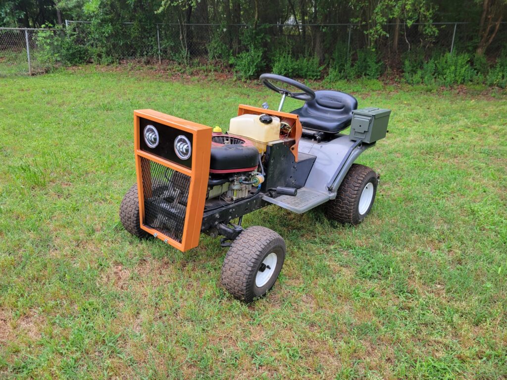
Paint
I eventually got the bodywork to a point where I could paint the remaining parts. I took the wheels, running boards, and fender off. I used bondo to fill in some of the areas where I removed or reshaped metal, such as around the shifter. From there, I sanded the areas smooth and applied a primer. Then shot a nice coat of orange paint.
The wheels got a black out look to get rid of the ugly white color. The running boards also got some black on the inner section. This turned out pretty good. The hitch and remaining hardware got a flat black spray.

Exhaust
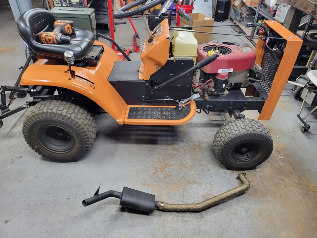
I wanted to make a custom exhaust for the Mow-Kart and remove the existing restrictive muffler. Once the original muffler was removed, I was able to take a section of steel pipe and begin making pie cuts to shape it down and under the right running board.
I started with the pipe coming straight out from the engine block and making a nearly 90 degree turn. I made a series of small cuts and bent the pipe until the angle was correct. This would’ve easier if I had a tubing bender, however I do not.
I then followed the pipe down until it needed to make it’s next bend, then made a series of more cuts until it matched the profile I was after. I wasn’t sure if I was going to use a muffler or not. I’ve been around some quiet single cylinder engines before and planned to not use a muffler. I did however, leave a section of straight pipe in the event I would run a muffler later on. And it’s a good thing I did this, because straight pipe was a terrible idea.
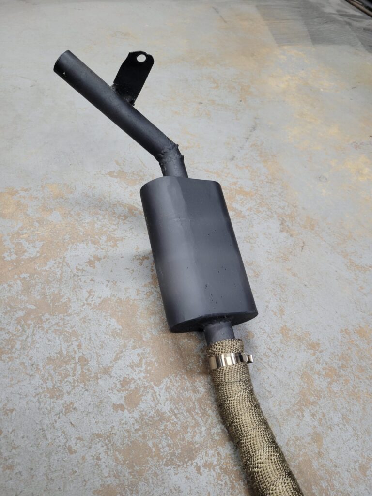
I ran the pipe out the side and welded a small bracket to secure the pipe. After a quick test drive, I realized straight pipe wasn’t going to happen. The motor would pop and bang and it was too loud overall. In keeping with the style, I opted to make a mini “Flowmaster” look alike. It would be a simple chambered muffler of my own custom design.
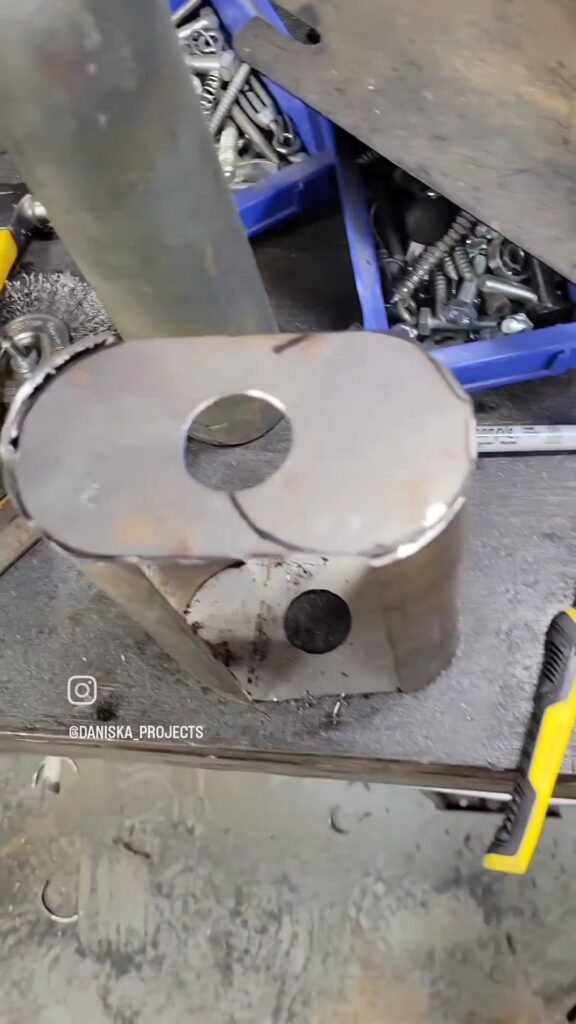
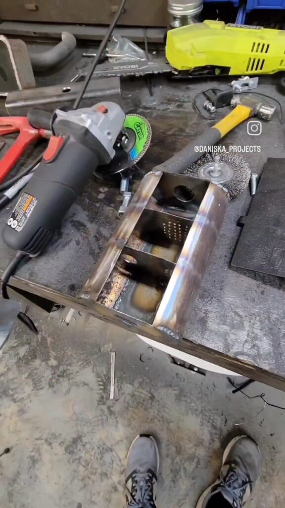
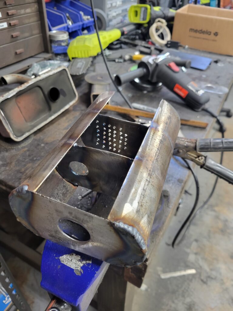
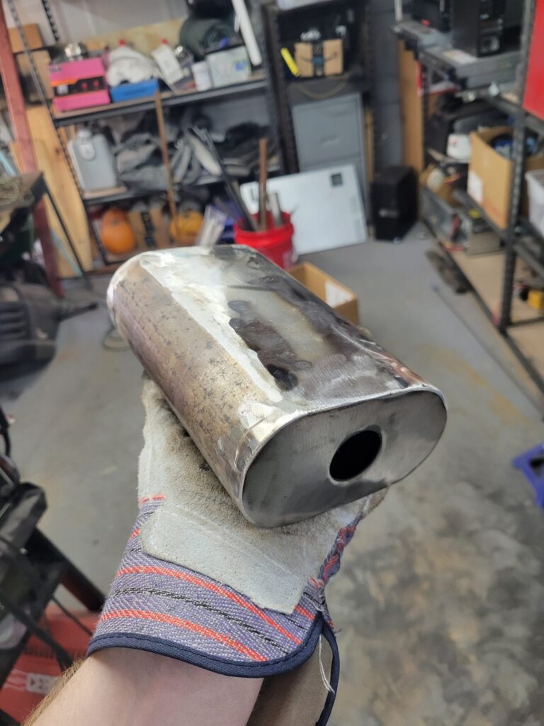
The muffler was made from a section of 2.5″ exhaust pipe that I cut in the middle. I then added sheet metal to make it oval shaped. The ends cap the whole thing up and the inner chambers are a slightly smaller oval piece of sheet metal.
I used some quick math to figure out a rough chamber length to cancel the sound without restricting the flow.
Front Bumper & Winch
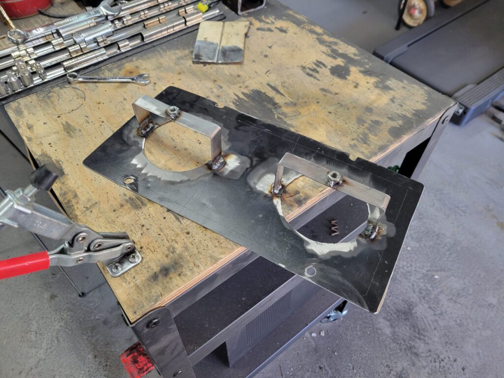
The next addition was a bumper and winch. The bumper would be the mounting point for the winch so they were added at the same time. The bumper is a simple 2″ square tube attached with 1″ square tubing. Working around the grille was tricky since the mesh was in the way. Getting around this involved cutting holes in the mesh allowing the mounting brackets to stick out from the frame.
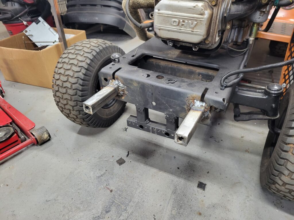

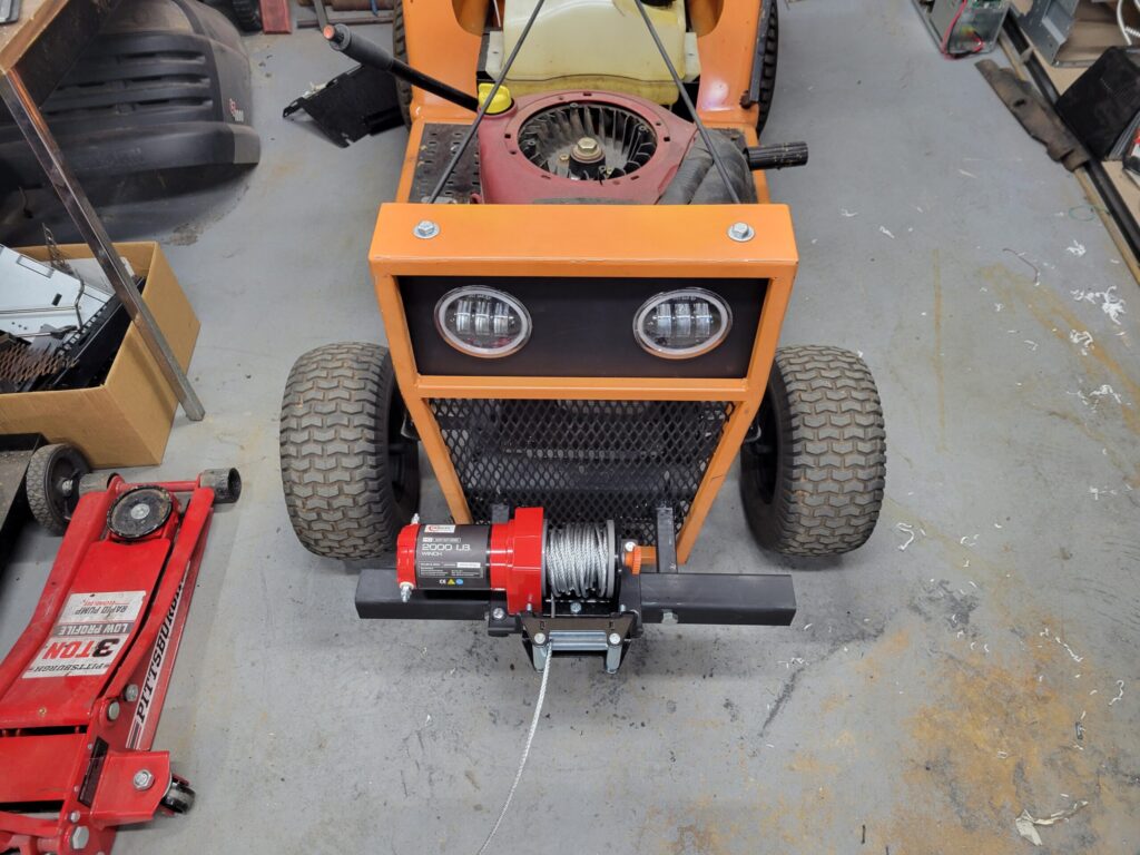
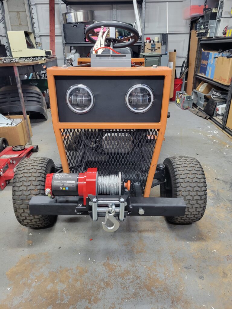
Tabs were welded to the bumper to allow a mating surface for the winch mounting plate provided. The bumper itself attaches using bolts so it can be removed if the grille needs to be removed.
Metal cross-braces were also added just behind the bumper mounts further reinforcing the frame. The bumper should be structurally sound and be solid to the frame. Once welded, the hole assembly got a shot of flat black to finish it off.