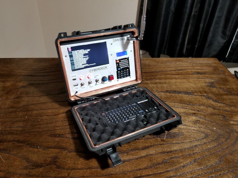
A Cyberdeck is small portable computer that, generally, is a homebrew machine. Even modern hardware, such as netbooks and laptops can stretch the aesthetic and be called a Cyberdeck. Typically, Cyberdecks are no more than glorified Raspberry Pi cases with built in keyboards. The term “Cyberdeck” originated in Sci-Fi novels written by William Gibson. Cyberdecks are generally built to fit the Sci-Fi Cyberpunk genre aesthetic so I knew kinda what I wanted it to look like, but what would be it’s purpose? I didn’t want to build something that was completely useless, just a little bit useless. but something with a more practical aspect. Since I’m working on some other projects involving amateur radio, I decided to put a handheld radio in the Cyberdeck and connect the I/O to a USB audio card controlled by a Raspberry Pi.
To use what I already have and to reduce cost, I used one of my Raspberry Pi Zeros. This model has a very small form factor, being about half the size of a Raspberry Pi 3.
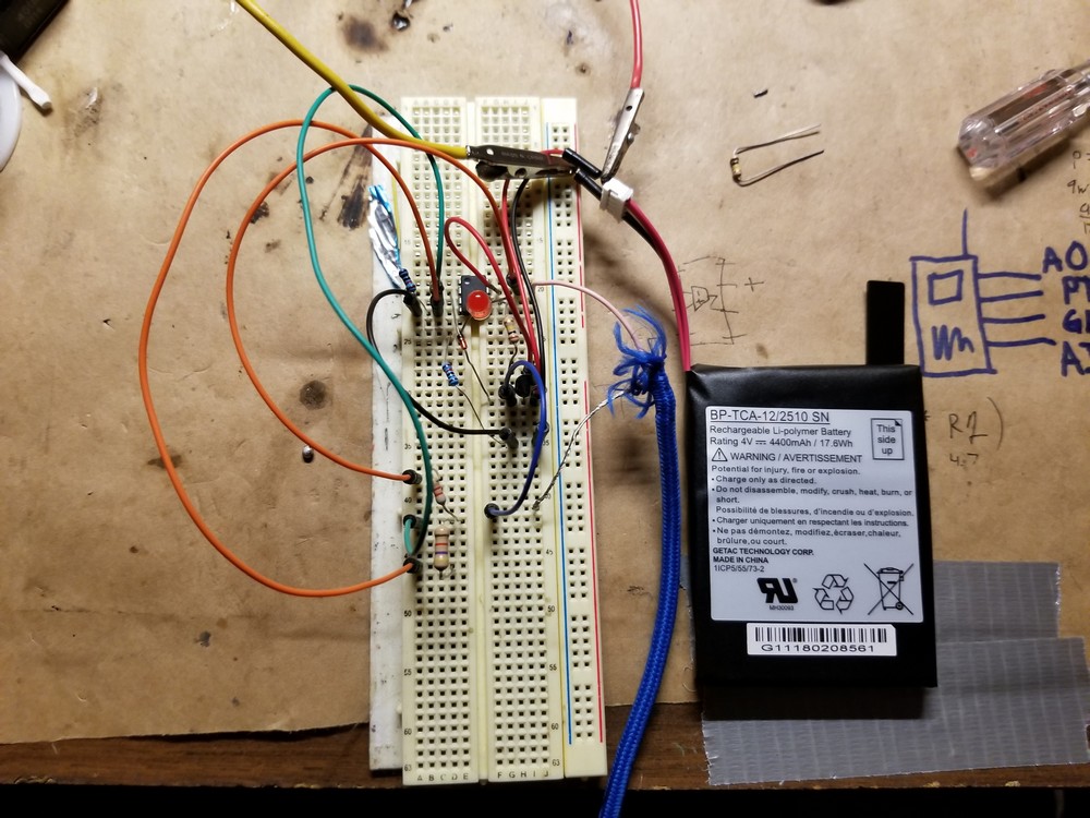
Power Distribution
Below is a simple block diagram showing the main components such as the Raspberry Pi Zero and the UV-5R VHF/ UHF transceiver. One of the main challenges with this build was the voltage difference between the radio and the Pi. The Baofeng radio has an input voltage of 7.4V while the Pi uses 5V. A separate charging circuit was used as the radio’s power supply. Pulling from the 18650 batteries in series to double up the 3.7V batteries.
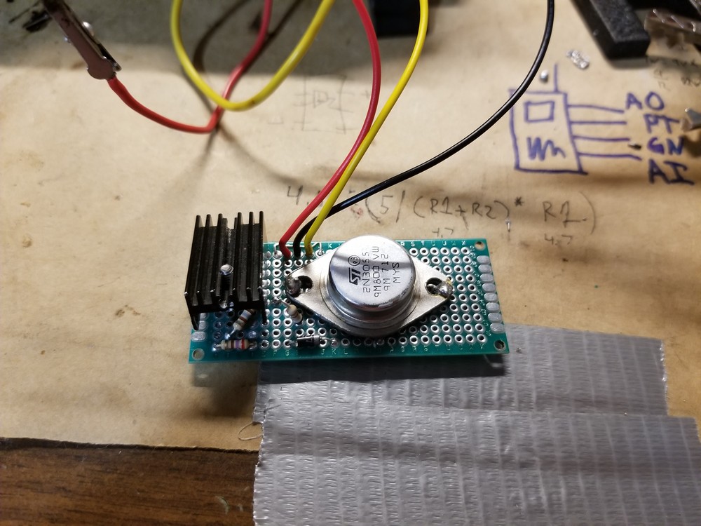
I tested several circuits to stabilize the output voltage and reduce the load on the voltage regulator. I’m using an LM7805 to maintain a steady 5V source.
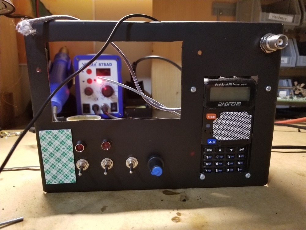
Case & Panel
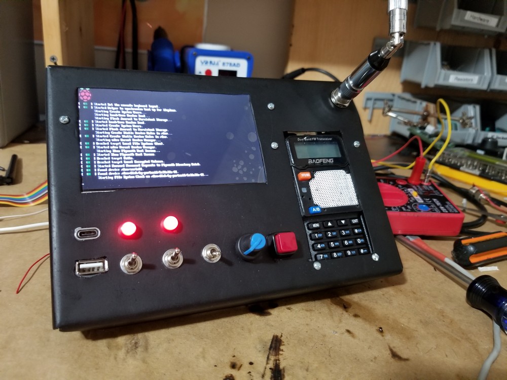
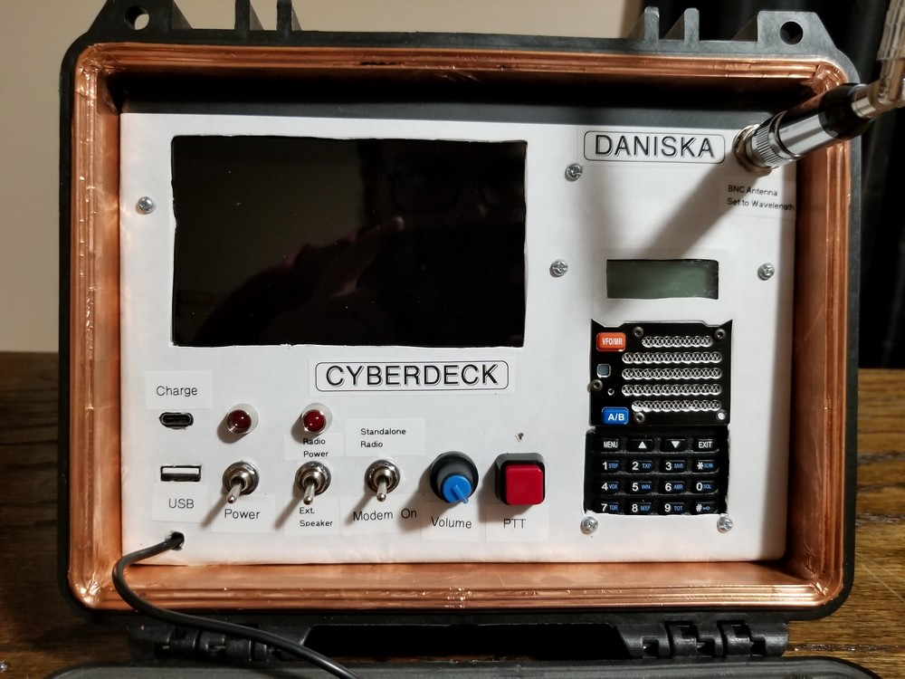
I cut the frame out of sheet metal and folded the edges down to fit in a small Pelican hard case. I don’t have the dimensions documented, but measuring the inside diameter and subtracting the thickness of the metal, will get pretty close to where the bends should be. With a tight fit, it ensures no components move around, while still allowing for removal if need be. I made a large cutout for the display and another for the radio. I had originally wanted to build a custom button panel for the radio, but due to the added complexity, I decided to keep it simple and use two cross-members that fasten the rear of the radio to the frame.
The three toggle switches control the power, the radio’s power, and the radio’s input selector. The first switch, the power switch, controls the main 5V power going to the Pi and to the screen. The radio power control turns power on to the radio and when off, uses the radio’s speaker as an external speaker for the Pi. The third switch controls the radio’s input. This selects from the USB modem or from the radio’s mic. The ham radio can still functions entirely as a standalone radio without the Pi. The front panel also includes volume control and a PTT button for use with the radio in standalone mode.
Antenna
The final item on the front panel is the BNC connector for attaching a variable length antenna. Once connected, the antenna would need adjusting to some fractional portion of the wavelength on a particular frequency. For example, If I’m transmitting on the UHF calling frequency of 446MHz (with a wavelength of 0.673m ), a 5⁄8 wavelength antenna would measure 0.421m. Different antenna lengths can be used with varying SWR. The closer the SWR is to 1, the better.
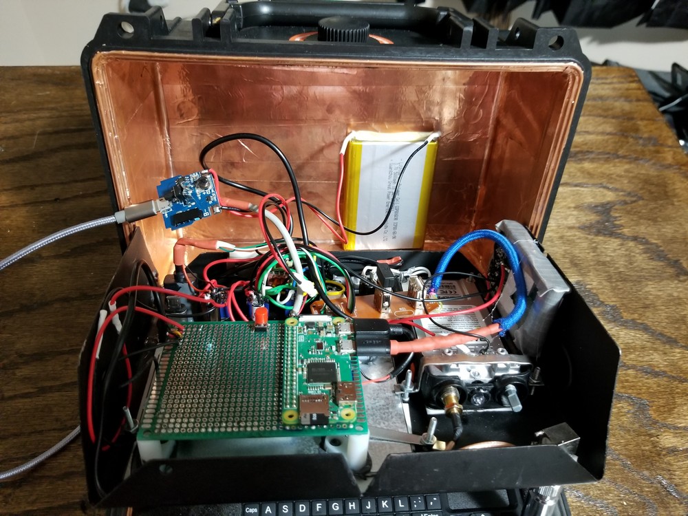
I lined the inside of the Pelican case with copper foil tape. Generally I use this to line the cavities of my guitars to reduce EMI. In this case, I’m reducing the interference caused by outside radio waves or potential EMPs. The composite video line from the Pi to the display also benefits from the shielding as it is very susceptible to interference. Especially with the antenna feedline passing right next to the display. Interference is noticed when transmitting in the form of a very choppy signal.
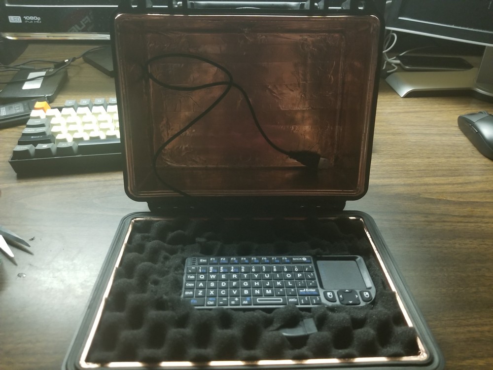
Keyboard
I had some difficulty finding a keyboard small enough to fit in the case while still being usable. Due to this constraint, I opted for a “media remote” type keyboard. This comes with a full keyboard and trackpad, but in a very small area. Typing commands has proved very difficult, but I hope to better utilize the GUI to reduce the typing. This unit can also be thought of as just a RTTY box. An external keyboard could also be used in conjunction to allow for faster typing.
I went through several battery options trying to find a simple, suitable option. Sharing power between the radio and the Pi proved nearly impossible with my setup. The UV-5R Baofeng is a 5W radio and draws roughly 1A when transmitting. The power draw would pull from the Pi and cause the Pi to shut off due to a voltage sag when transmitting.
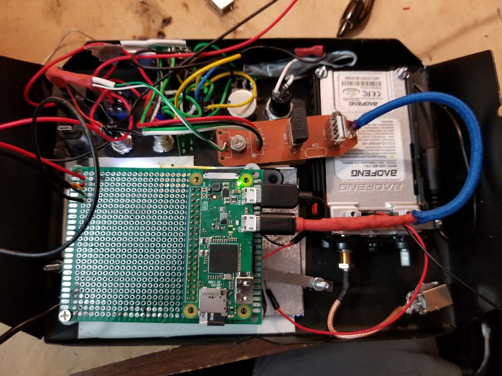
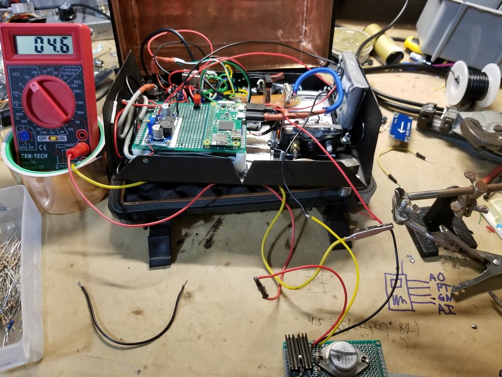
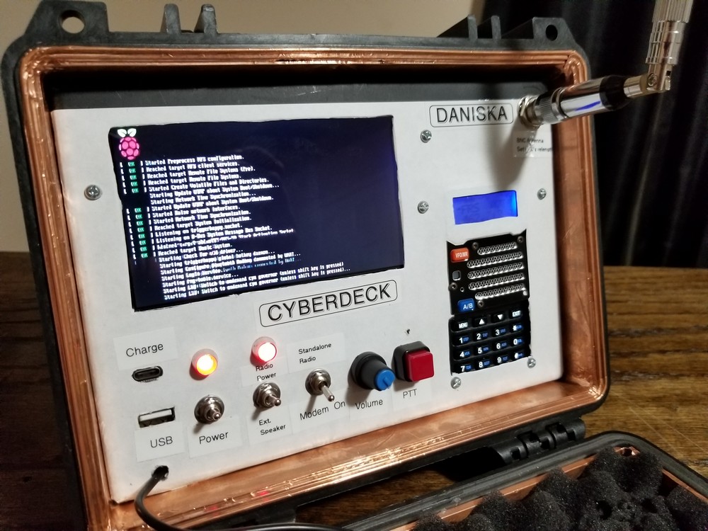
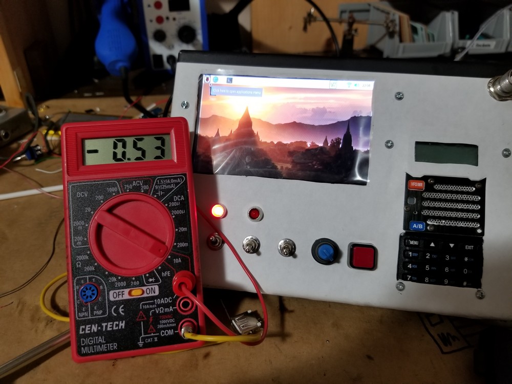
Here is the Pi booting up and the current draw of about 530mA at idle. During testing, I used another ham radio with an adapter plugged into my laptop to test the minimodem software.
Software
The modem software I’m using is called minimodem. This is a simple FSK modem software that takes data and outputs audio. This output is then fed into the mic of the radio. For the opposite, the headphone output of the radio can be fed into the audio input of the USB soundcard that is plugged into the Pi. This can then decode the incoming data. To install minimodem on a Pi or other Debian system, issue the following command.
sudo apt-get install minimodem
Basic example is to send ASCII data using sound that is transmitted over the radio. Here is a simple RTTY command to send some text. After this command is entered, text can be typed and trasmitted.
minimodem --tx rtty -a
hello world
And the opposite to receive ASCII data is to use the RX switch.
minimodem --rx rtty -a
This project demonstrates how something built primarily for aesthetics is made into something more practical. This Cyberdeck would be useful in the aftermath of an EMP