
A solder reflow oven is a device used in the process of assembling printed circuit boards (PCBs). It is designed to heat up the solder paste on a PCB to the point where it melts and forms a reliable connection between the components and the PCB. The process of reflowing solder in a PCB assembly is an important step in the manufacturing process, as it ensures that all the components are securely attached to the PCB and are electrically connected.
There are several different types of solder reflow ovens available on the market, including convection ovens, infrared ovens, and vapor phase ovens. Convection ovens use heated air to reflow the solder, while infrared ovens use infrared radiation to heat the solder. Vapor phase ovens use a combination of both methods.
Initial Design
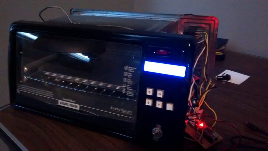
This project uses a cheap toaster oven as the base for a reflow oven capable of reflowing PCBs reliably. The original prototype for this project used an ATMega8 MCU at the core. The later board used an Arduino Nano.
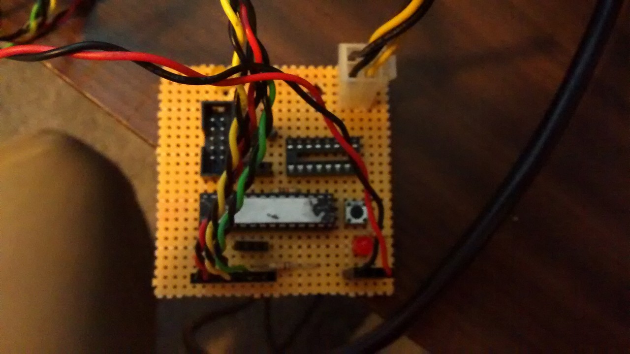
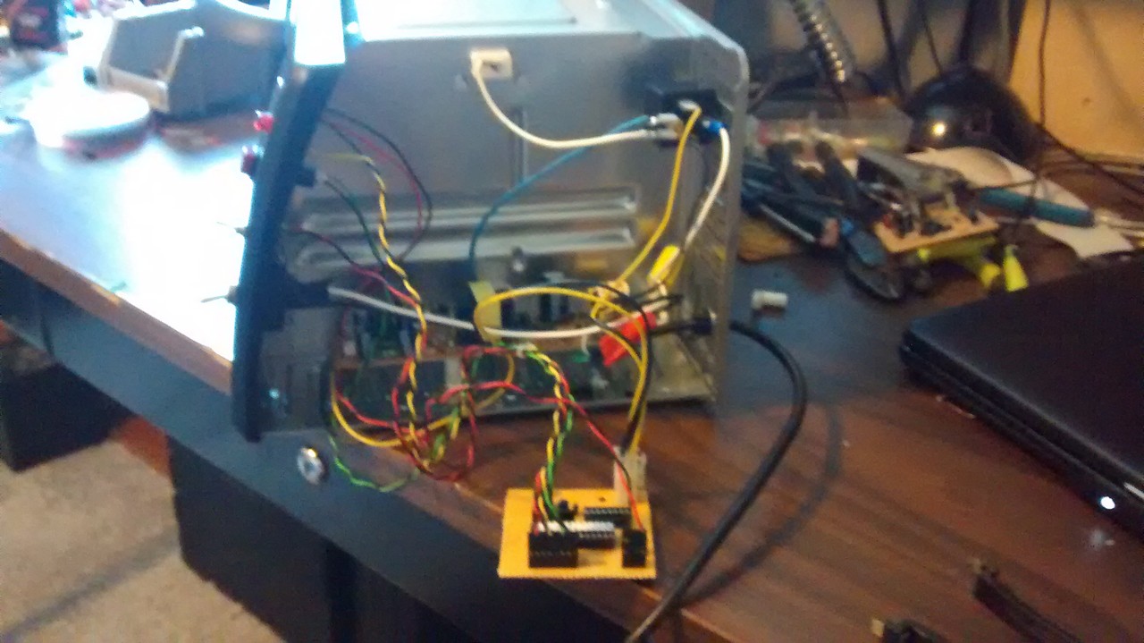
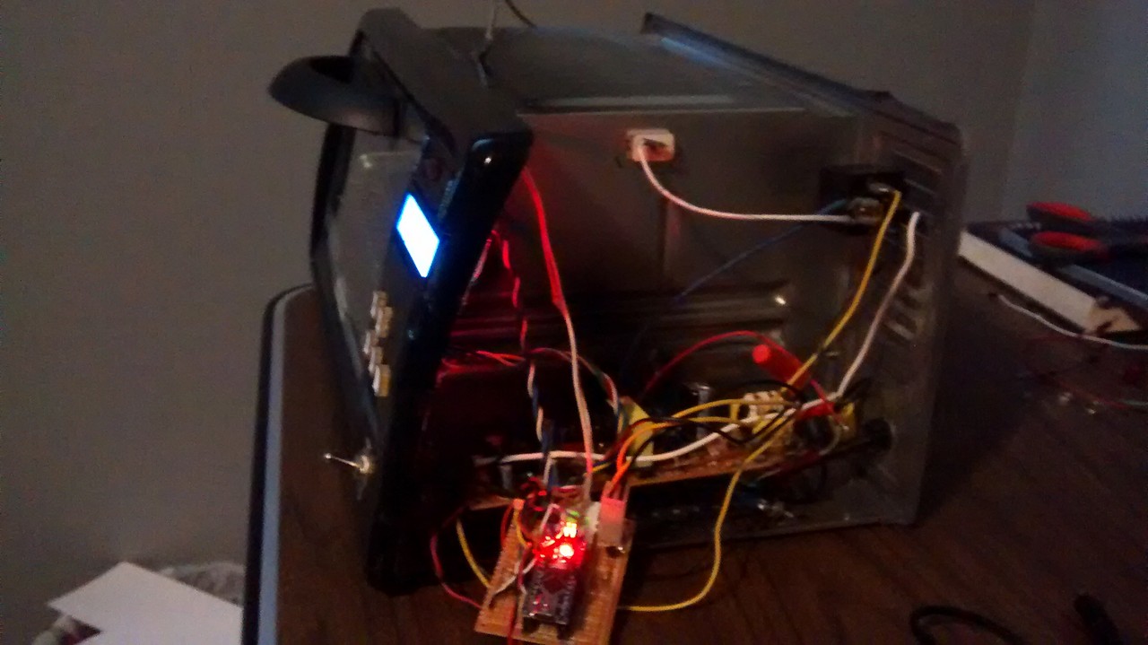
The inside of the toaster oven was very simple, but everything needed to go. I added a master power switch and then a 5 button cluster with an LCD. On the inside, the heating elements were connected to power using a relay rated to switch the high load. There is an NPN transistor that drives the relay using the Arduino. To measure the temperature of the oven, an I2C thermocouple is used. An old power board is mounted on the bottom to provide 5V/12V for the Arduino and relay.
Testing
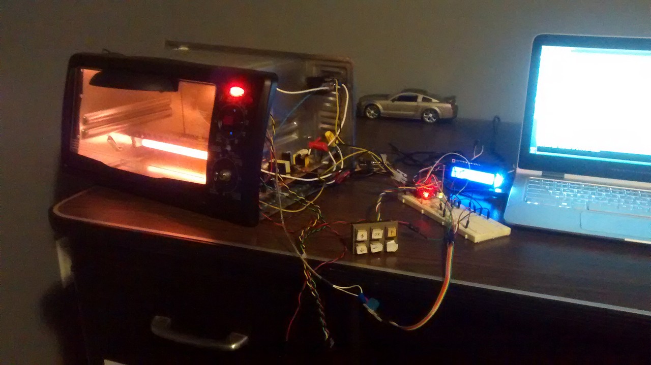
Here is the oven during the initial testing of the components. My first goal was just to get the relay to cut on and cut off automatically using the temperature reported back. I wrote a simple program that reads the temperature and cuts the heat when a set number is reached. This is no where useful for my application, but is a good demonstration of how the device functions.
Custom Front Panel
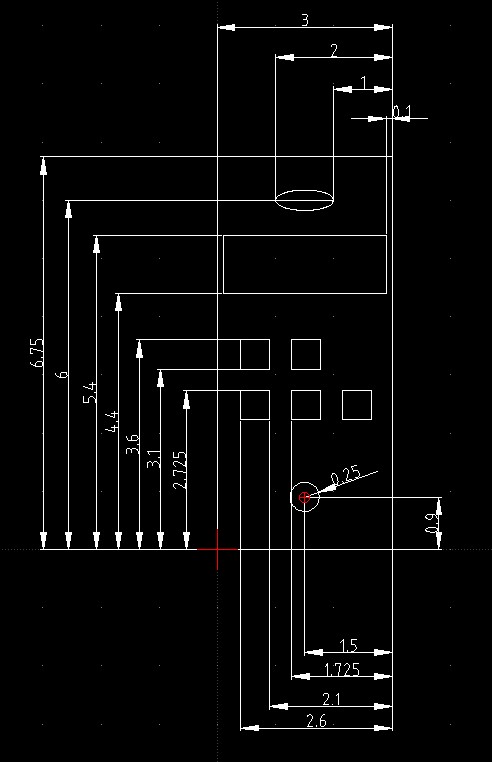
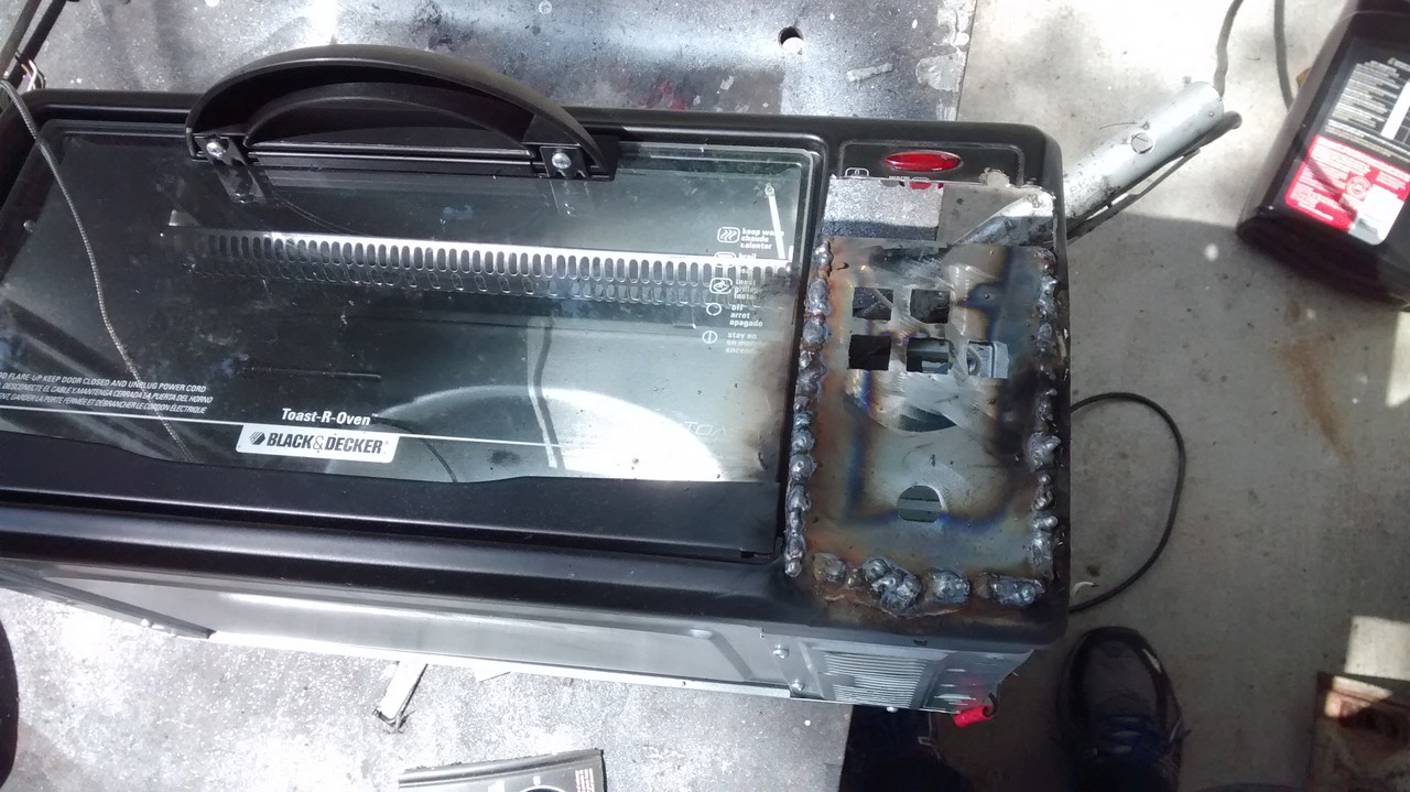
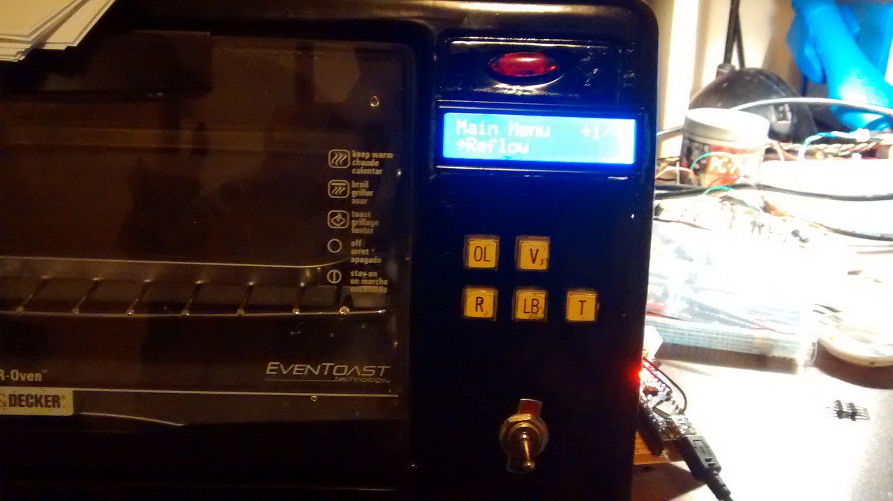
I designed a front panel for the oven and cut out the design in a piece of sheet metal. I made room for the LCD, buttons, and the power switch. These buttons actually came out of a vintage EEPROM program I scrapped.
Here I’ve laid out the design in CAD.
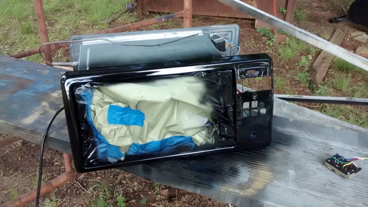
After getting everything cut out and welded in place, I put a nice coat of semi-gloss black paint onto the entire front.
The next goal was to get the buttons and LCD to operate as intended. I planned on several “routines” that would run. As well as adjustable variable in the solder reflow profile. This would all need to be controlled from the LCD.
Arduino is based on the AVR plateform, so coding with Arduino allows for easy implementation. Below is my GitHub for this project
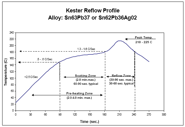
Reflow Profile
Solder reflow should be heated in a controlled manner to ensure that the solder paste is melted evenly and reliably forms a connection between the components and the PCB. If the solder is not heated evenly, it can result in incomplete or faulty connections, which can lead to problems with the functionality of the finished product.
To achieve a controlled heating of the solder, most solder reflow ovens use a heating profile that specifies the temperature and time at each stage of the reflow process. The heating profile is typically programmed into the oven and is based on the specific characteristics of the solder paste being used.
By following a controlled heating profile, the solder reflow oven can ensure that the solder paste is heated in a consistent and reliable manner, resulting in high-quality connections between the components and the PCB. Overall, the controlled heating of solder during the reflow process is essential for ensuring the reliability and functionality of the finished product.
Overshooting. PID?
The hardest part of this project was the thermal lag of the oven. Overshooting has been a large issue and and I have thought about implementing PID. Proportional-Integral-Derivative, control is a control algorithm that is commonly used to control the temperature in processes such as soldering and welding. It is designed to help maintain a consistent temperature by continuously adjusting the heat input based on the difference between the target temperature and the current temperature.
One of the main advantages of using PID control in the heating process is that it can help prevent overshooting the target temperature. When using PID control, the heat input is adjusted in proportion to the difference between the target temperature and the current temperature. This means that as the temperature approaches the target, the heat input is gradually reduced, which can help to prevent the temperature from overshooting the target.
In addition, PID control also includes an integral component that helps to eliminate any steady-state error between the target temperature and the current temperature. This can further help to prevent overshooting and ensure that the temperature remains close to the target.